Mini MiniMig
This project is a development of the original Minimig made by Dennis van Weeren. This time, I'm trying to make it
as small as possible as a part of a mobile version. Still, all features of the original version are kept and a few new things are added. To reach this goal, several tricks have
been used, resulting in a board size of 110 x 65 mm (the original Minimig is 120 x 120 mm and my Mini-itx version is 170 x 170 mm):
- 4-layer board is used: This is a first for me, but was required to get everything routed on that small space.
- Double-sided mounted parts: I'm using both sides of the board to squeeze in all components.
- Headers instead of connectors: Standard pin headers (2.54 mm spacing) are used to all ports to save space.
- New memory chip: The two 512k x 16 have been replaced with a single 1M x 16.
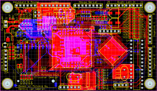
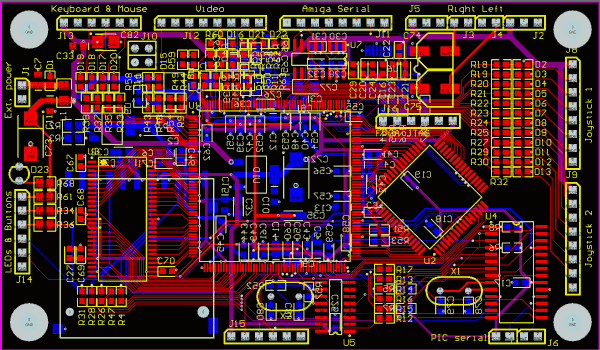
- Tight routing: All parts have been squeezed together and 0.1 mm routing clearance are used.
- FPGA pin change: I had to move around with the pins on the FPGA to optimize the routing.
Even with this tight design, I managed to squeeze in both a headphone amplifier with DC-controlled volume (doubles up as a line level driver) and a RS232-driver for the
Amiga serial port. Even the FPGA JTAG survived the squeeze and there are four optional FPGA pins avaiable for own usage. I also managed to keep the original clock oscillator
and crystals (both for the Amiga clock and the PIC). The ESD protection has been improved too. The ISP for the PIC18F252 have been removed compared to my previous board.
It did not work at 3.3V anway. The serial port from the PIC is still there but it requires an external level converter (it is used for development and debug, so there are no big deal).
This version of the board will run the unmodified FPGA and PIC code, but as I have changed the pin layout for the FPGA, a recompiled version of the MINIMIG1.BIN is required
where the pin assignment has been changed. I will make it available here when it has been tested. The PIC must be programmed with the code (or at least the TinyBoot) before it
is mounted at the board (a small drawback with the tight design - a DIP-version was too large). With TinyBoot, it will be possible to update the PIC firmware via the serial port.
Edit:A small change to the text above: I managed to squeeze in a DIP-sized PIC on the board without changing it's size. So, there is no problem to reprogram the chip in case no bootloader
is used or if the bootloader is wrecked in some way (or a new version appears).
The idea behind this Minimig version is to provide it as a module, usable for different applications where space matters. It is possible to use it as a generic FPGA application
board too. In that case, you will have twelve additional ports via the joystick headers.
Board specifications
- FPGA: Xilix Spartan-3 XC3S400
- Loader: PIC18F252 using standard MMC/SD card
- Memory: 2 MByte (1M x 16) 10ns SRAM
- CPU: Freescale MC68SEC000AA16 (16 MHz low-voltage MC68k-clone)
- Power: 5.0 V only (on-board LDO regulators creates the needed voltages for FPGA and logic)
- Video: 12 bit via simple resistor D/A (4 bits/color)
- Audio: LM4834 headphone/line amplifier with DC-controlled volume
- Serial: MAX232 compatible level converter
Files to download
Updated 2008-06-15: An updated version of the Mini Minimig have been designed. The function remains the same, the difference is the change from a SMD-mounted PIC to a hole mounted.
The reason for this is simple: If the PIC needs to be reprogrammed, it must be removed from the board. It runs at 3.3V, and at that voltage, the bulk erase will fail. The original
idea was to build a rig to pre-load the PIC's with the Tiny PIC bootloader. But if the bootloader fails in some way and the PIC must be reprogrammed, you will end up with a unusable
board. By having a hole mount PIC, it is possible to use a socket. This allows the user to remove the PIC and reprogramming it in the usual way (using a Wisp and a breadboard for
example).
When I was playing around with the PCB layout, I did some more changes too - not functional but layout related: Additional ground planes have been added to sensitive areas at the component
side; the routing between the PIC, the FPGA and the SD-card socket have been cleaned up; additional copper areas for cooling the regulators ave been added.
Update 2008-06-19: A first set of five boards have been ordered at PCBCart. These are the first prototypes that will be
done for evaluation and testing. If they work fine, they will be the base in developing a console MiniMig and a portable unit. To accomplish that, three different motherboards or
"decks" will be developed. The first one, the Test Deck, is ongoing. This will be used to test all features of the board. It will basically give me a standard MiniMig with S-Video output
at a Eurocard-sized board. The other two will be modified versions of the Test Deck, adapted to the specific usage and size.
Update 2008-07-08: The boards was finally delivered. Five of them in a neat package from PCBcart.com. Initial testing shows that the power supply lines and the ground plane are
correct. Now, I must order more components to put these together...
Update 2008-07-13: One board alomst completely assembled. Power part tested ok with FPGA, CPU and memory fitted. No sign of high current draw due to faulty parts or short circuits.
Now, I need the test baseboard to continue. Due to vacations, this will take some time.
Update 2008-12-26: It took a while due to several reasons (my mother, the Mini-ITX MiniMig, work...), but this tiny beast is finally alive. The first tests have been done and it looks fine.
I managed to rebuild the FPGA core with the swapped pins and the board did boot up as it should. Played some Silkworm and Turrican on it too. The audio section still needs some investigation
as it is just silent for now. All other parts works fine (joystick, mouse, keyboard and video).
What's next? Re-design the board to use an other SD-card socket as the current one has gone out of production. I may also change other things to keep it up in par with the Mini-ITX model.
We'll see what the future will deliver...
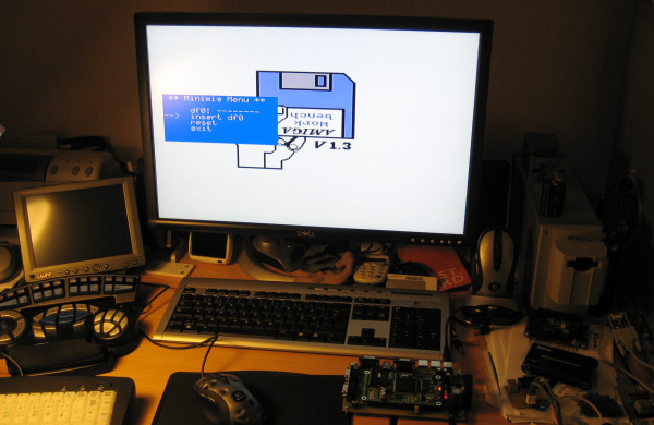
First boot up - it just feels good that all effort and costs involved in this design wasn't just a waist...
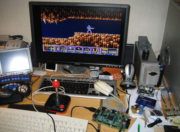
Some Turrican fun going on...
The board is placed on a test deck specially built to verify all functions.
Almost complete board - and better light too...
Things are getting together (parts still missing)
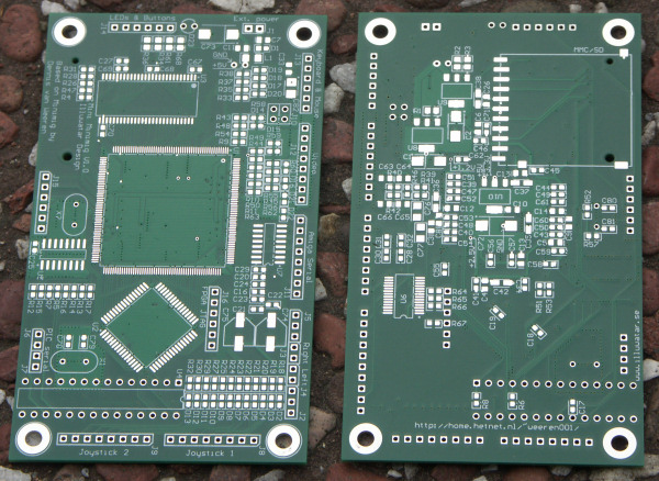
The first boards made. Time for testing...
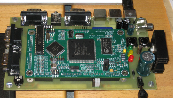
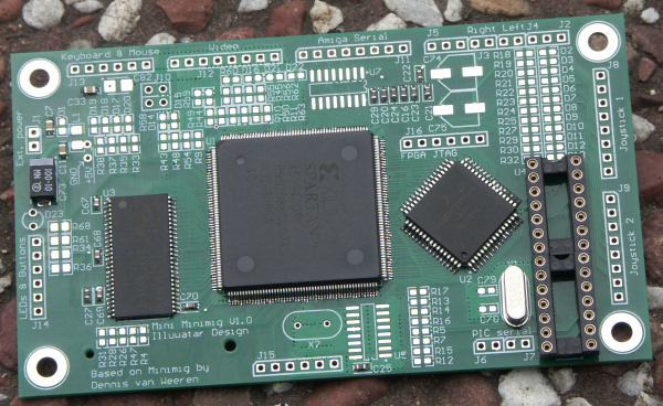
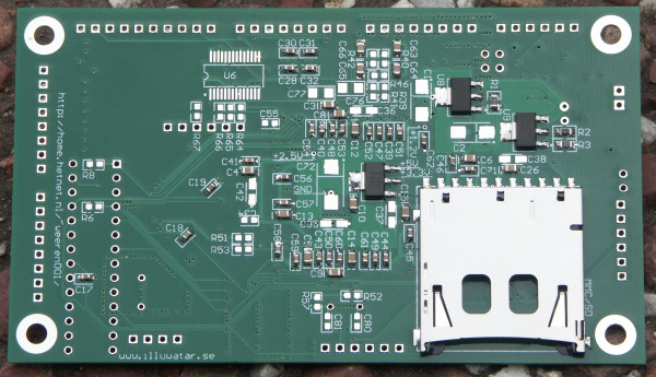
Updated version with hole mounted PIC.
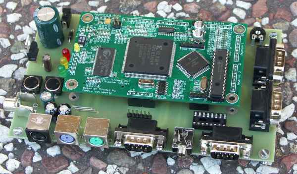
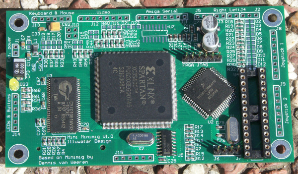
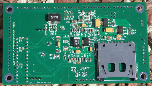
First version, using a SMD PIC.