The Georg Braun A1000 build project
This project is all about nostalgia. It started with a thread at Amiga.org, created by a member called Kristian95. His idea was to order unpopulated
PCB's made from the plans created by Georg Braun. The special about these boards and the design is that it re-creates the classical Commodore Amiga 1000 with some major improvments. You may wonder why
not stay with the MiniMig, but there is a significant difference. The MiniMig emulates the OCS Amiga 500 by using an FPGA containing code that are based on reverse-engineering. This Amiga 1000 reincarnation
uses the original chipset from actual Amigas, making the result 100% Amiga-compatible (the MiniMig does have it's flaws in the emulation). Still, this design aren't a blue-copy of the original Amiga 1000
machine: several enhancments have been implemented by Georg (features that normally comes as expansion boards). This includes 68030/68882 CPU setup, 32 bit memory, IDE-controller and a flicker-fixer.
So, when I saw the thread, I could not resist to get in to it. As an old A500-user, this was a nice opportunity to play with the Amiga again, in a semi-modern way. In other words: one of the PCB's is
going to Sweden...
That makes this project little bit different from the other ones at this web page as it is not a design by me (or at least modified by me). But the build is certanly interesting and there are over 50
other buyers waitning for the PCB, so this is a way to share my experiences.
Short feature description of the GBA1000:
I will make a short description of the GBA1000-system. The full details is available at the official GBA1000 homepage together with pictures and
additional information.
- CPU: Motorola MC68030 at 40 or 50 MHz
- FPU: Motorola MC68881 or MC68882 at CPU-speed
- RAM: 8 Mbyte 32-bit SRAM, 2 Mbyte ChipRAM
- Chipset: ECS Amiga (ECS-Denise 8373 and Fat Agnus 8372/8375)
- Built-in flicker-fixer with VGA-output
- One Zorro-II slot
- 1 Mbyte Flash-ROM for optional software
- Real-time clock with battery backup
- IDE-controller
- Two Kickstart-sockets
- Fits directly into an original Amiga 1000 case
Project downloads:
- All GBA1000 schematics in high-quality PDF (7 pages): Download
- The assembly drawings of both sides, high-quality PDF (2 pages): Download
Project status:
2009-05-16: Back in to this project after a rather long pause. The DC/DC-converter (PSU) is on the track with PCB's ordered and delivered. The design haven't been tested yet as there are still parts
missing. Orders will be placed...
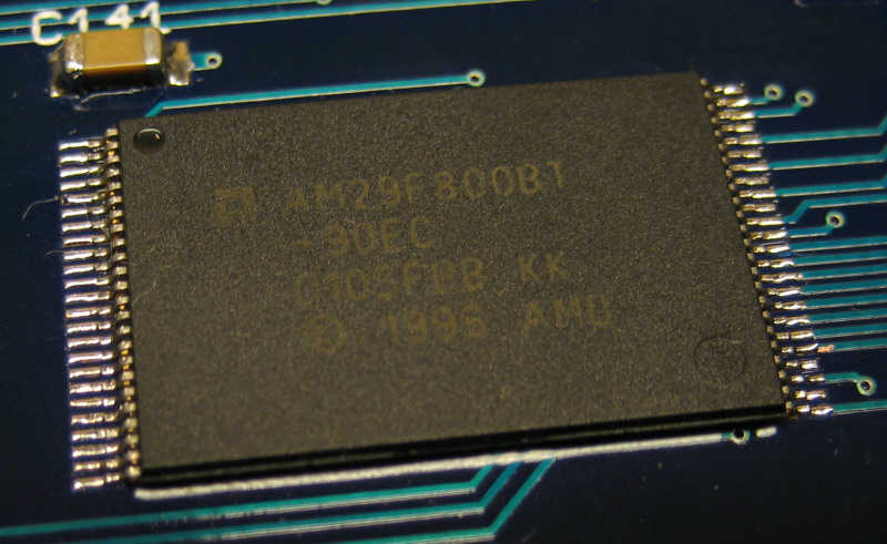
2008-11-26: The project progress is slow now. It has reached the point of almost completion. Only a few critical parts are missing. And I need a way to power it up too (that work is in good progress,
design almost done). A few and very important parts have been bought though: the memory chips needed by the scandoubler and the 29F800 Flash memory. That flash was packed in a TSOP package and it was a small
challenge to put in place. But I usually never give up:
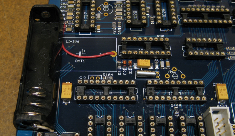
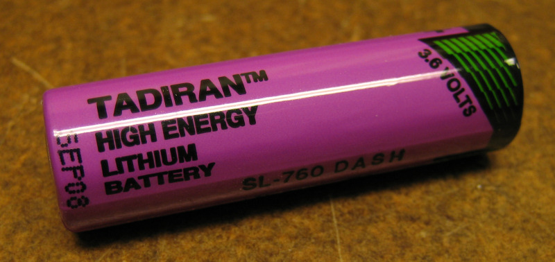
2008-11-13: The clock battery is in place. I used a different approach to this: instead of using a battery that solders directly on the PCB, I went
for a standard AA-battery holder. A 3.6V lithium AA-size cell will be placed therein. That makes replacement easier.
2008-11-07: Build progress is good, but there has been some delivery issues with some of the parts from Electrokit. A order has also been
placed at Elpro for these 5-pin SIL resistor networks (and some other stuff too). The board is at this moment about 95% done.
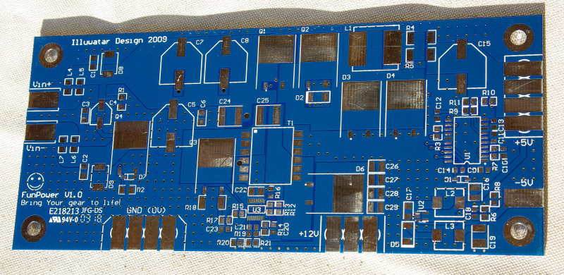
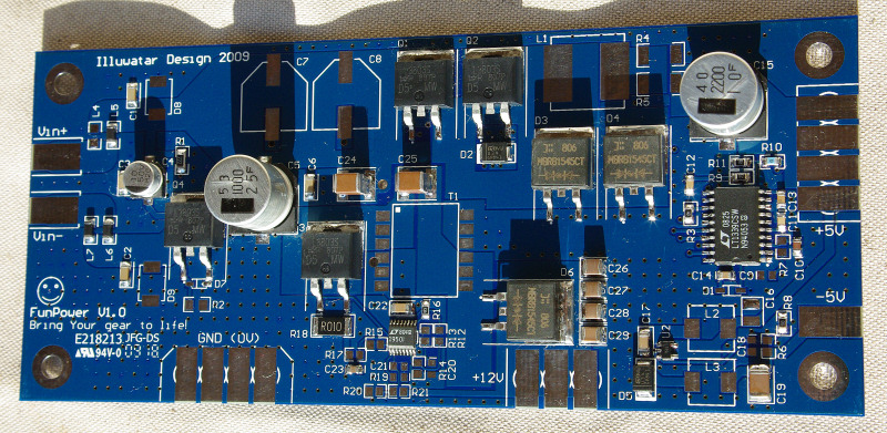
As I'm going to build a custom case for this machine, I don't have an Amiga 1000 power supply (PSU) available. So, I'm going to design one from scratch.
The idea is to use a powerful laptop style "brick" as the main power source. Using switching regulators will give me the voltages I need. Totally, three
different outputs are needed: +5V/8A, +12V/1A and -5V/0.25A, power rating is 80W. These numbers was read at an actual Amiga 1000 PSU (found a picture at the web).
My design will use a combination of step-down regulators for the positive voltages and one inverter for the -5V, making the design capable of running from a single
input. The heavy one (+5V/8A) will be handled by a LT1339 from Linear Technologies. This chip is a controller that requires external power transistors to operate.
By doing that, several hundred of ampere could be controlled. In my case, I will stay with 10A, giving me some safety margin. The +12V is easy in comparison: a Simple
Switcher IC will do that work. The negative output is still under investigation. Finally, a series of shots to feast Your eyes on...
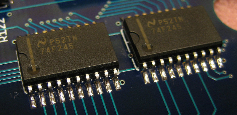
2008-10-28: Got the SMD 74F245 today, those I bought from US via eBay. Of course, they quickly found their proper places at the PCB:
2008-10-25: Board is closing in th completion. All EMI-filters are in place and most of the resistors and capacitors too. There are a few things
left that will be done when I get the delivery from Electrokit.
Only some few things left...
As I mentioned earlier, an Amiga 500 that is broken will support me with the needed connectors and the special crystal oscillator. The board is a very old one
from 1987, a Rev. 3 model. The Agnus was marked 8371 - OCS with 512k chipmem.
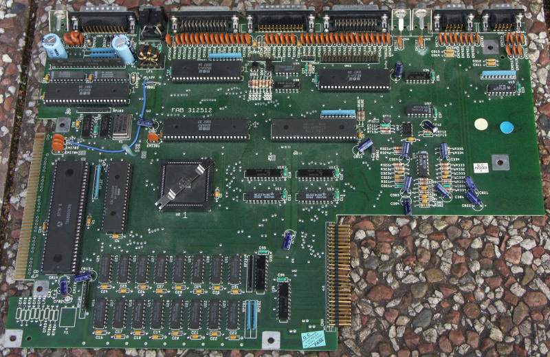
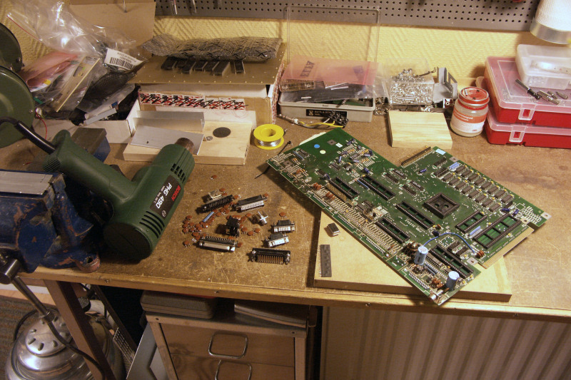
That poor Amiga did not stand any chance against the heat gun...
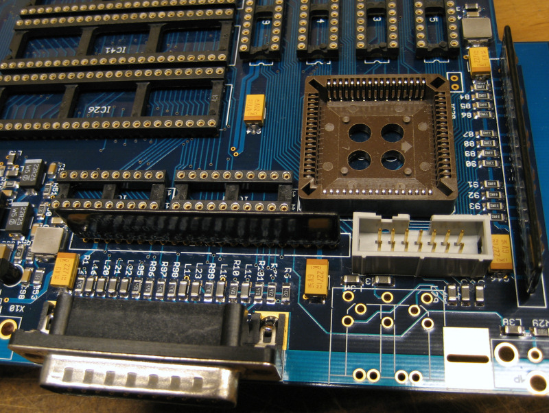
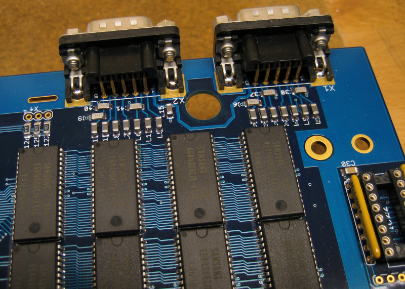
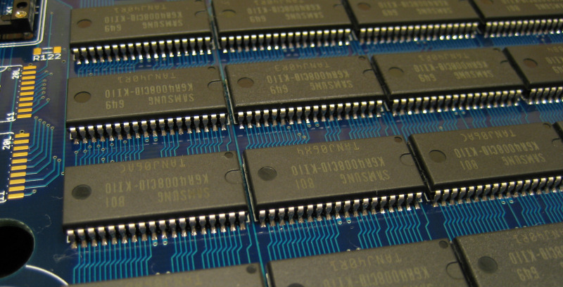
2008-10-20: All RAM are in place now at the board, in total 16 SRAM-chips. They took a while to put in place. Also, the final two large orders
have been placed at Digikey and Electrokit, so I will have almost all parts needed to complete the board. A old and broken Amiga 500 board has also been
purchased to act as a donor board for the connectors. The hunt for the hard to find memory parts used by the scandoubler is ongoing.
2008-10-13: Some more updates - more parts in place. Need to buy these odd value resistors, capacitators and try to find all EMI-filters needed.
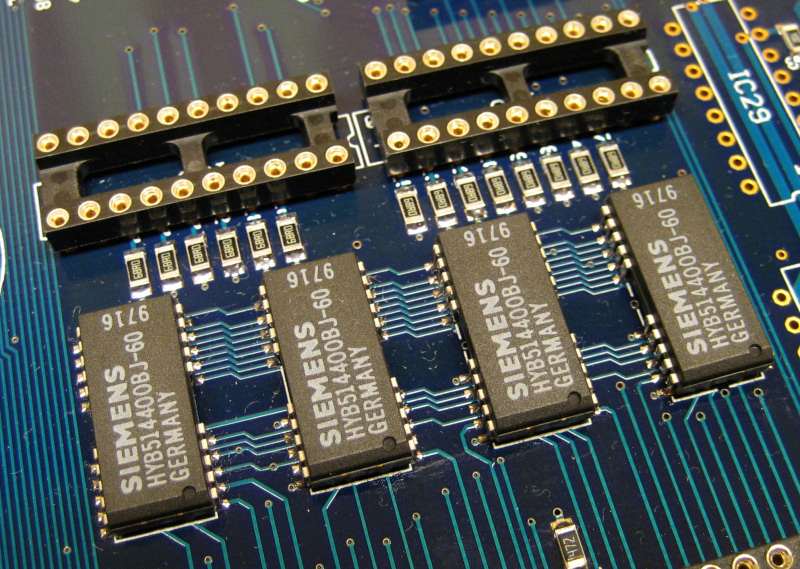
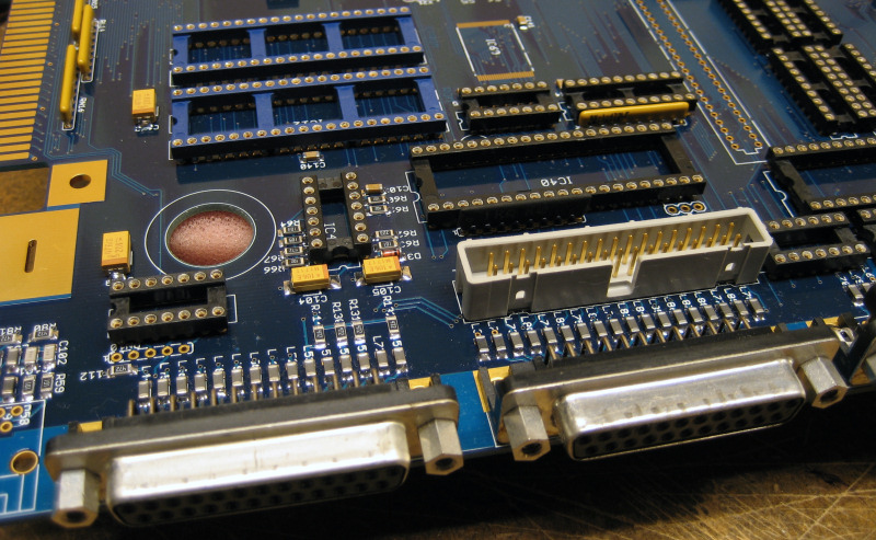
The Chip-Mem section
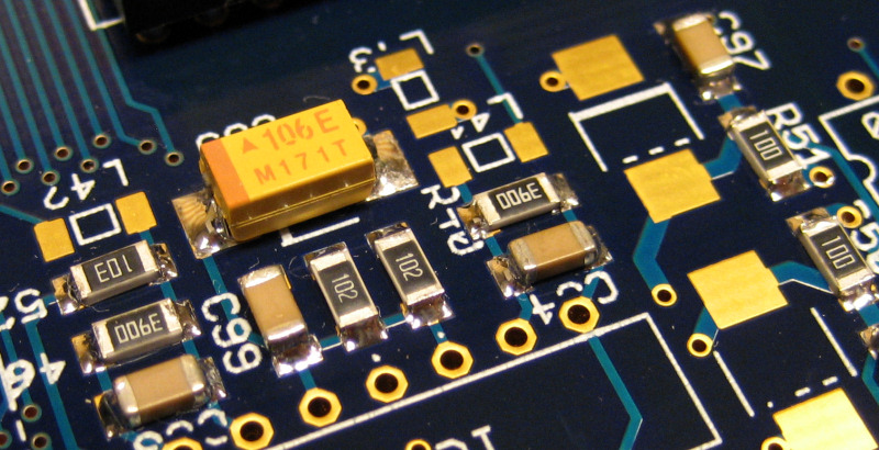
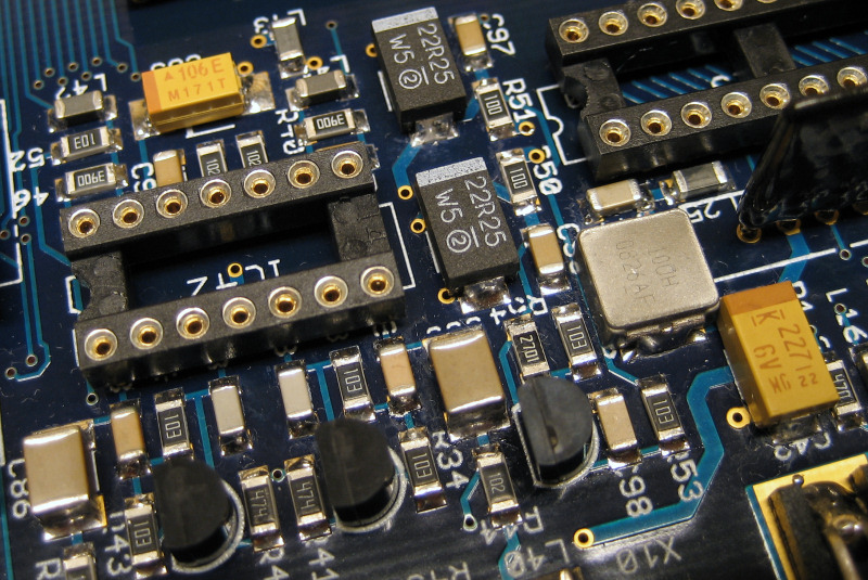
Part of the audio section
2008-10-11: Board assembly is ongoing. Also are more parts found and added to the project. This time, 8 MB 10 ns SDRAM and the 2 MB Chip-Mem together with some support IC's was received from
Kessler Electronic. These vintage designs aren't cheap - if you shell out about 80 on modern DDR2 memory to your gaming rig, you will
have about 4 GB (observe: Gigabyte). Or 400 GB if you are into a new harddisk instead... But who is building something like this to save money? Restoring old cars aren't cheap either - actually the
restoration alone costs more than the car when it was new. Enough with talk, bring the pictures instead:
The content in the order from Kessler Electronic.
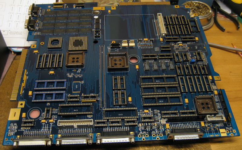
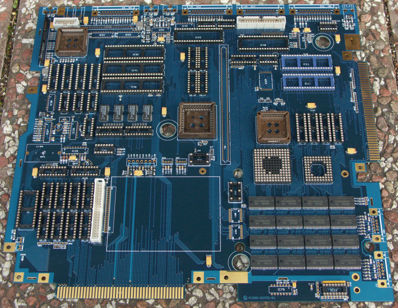
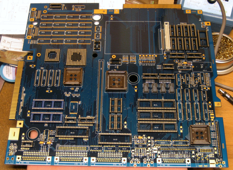
Current assembly progress of the board.
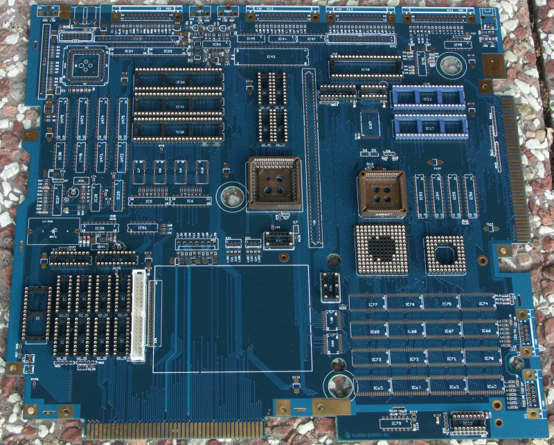
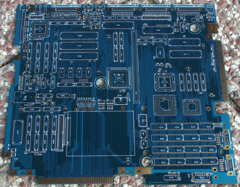
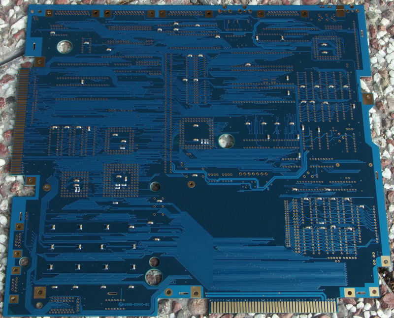
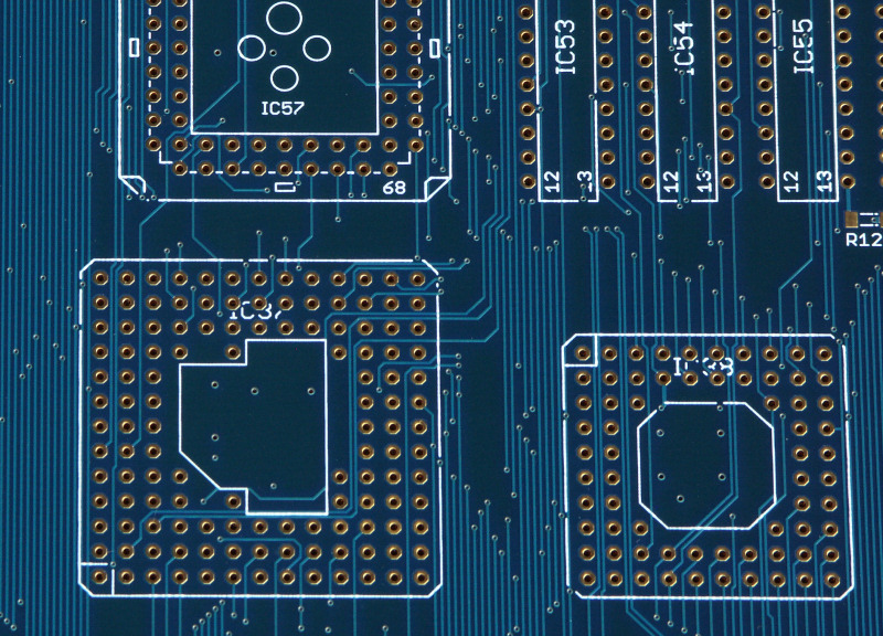
2008-10-06: Here are the board pictures:
2008-10-03: Created high quality PDF prints from the Eagle files supplied by Georg. These are available at the "Project download" section. These printouts are not resolution limited as these in the original German
handbook, so they can be printed as large as you like. The prints was done with size A3 as a base.
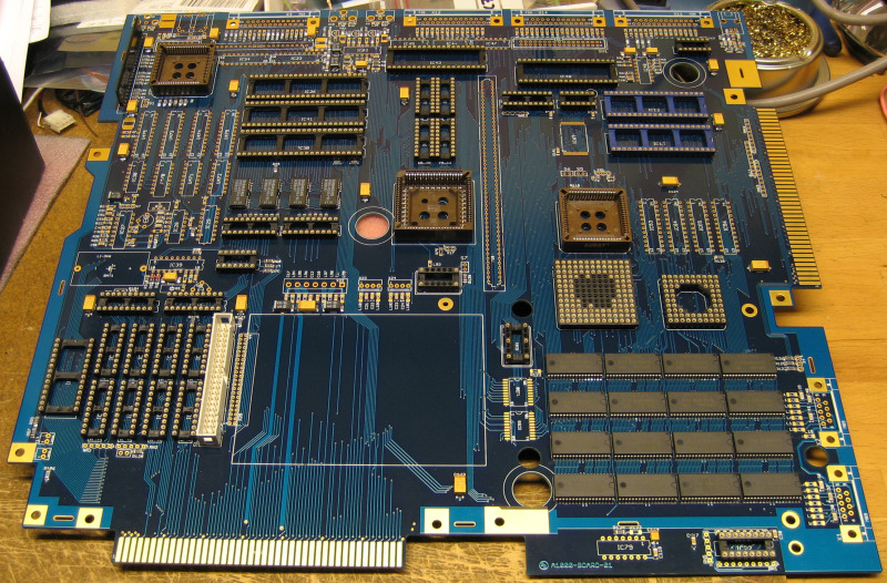
2008-10-02: Got my board today! Kristian did a serious job with the packing of it so there was almost impossible to destroy it during delivery. The board itself is just amazing with it's deep blue solder mask
and the gold plating (most of it will not be visible after the parts are added). So, the start of assembly will soon begin...
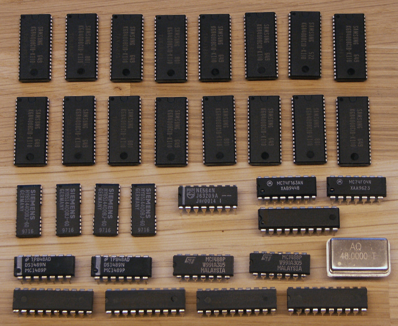
2008-09-30: Boards are on the way - fellow friends in US has already got their ones. But to the cold Sweden, it will take some more time. Until then, enjoy the pictures of the special parts needed for this build.
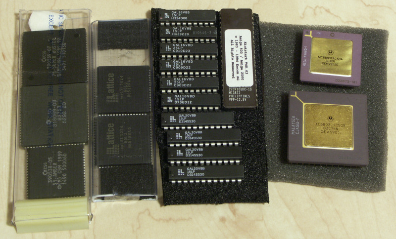
Some of the Amiga custom chips together with the 50 MHz CPU/FPU-set and the programmable logic circuits (GALs and Lattice ispLSI). Also, a Kickstart ROM version 3.1 (V40.63) have been bought.
A lot of these custom ICs are bought through eBay but there are also severals Amiga-unique shops that have these as spare parts.
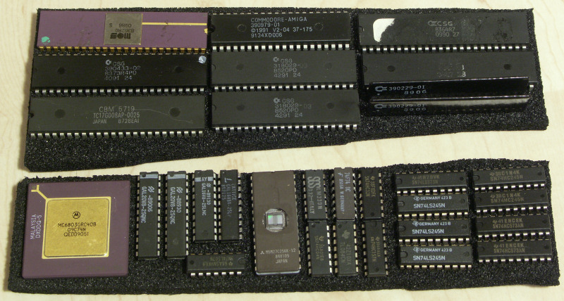
More CBM-chips but also 74-logic and some other misc. ICs. There are also some spare GALs and a 40 MHz 68030 that was first planned for the build. But now (when I found a cheap source of the 50 MHz parts) it is not needed
for the GBA1000 build. Instead, it will be used in my VXL-30 accelerator board that lives inside my old thrusty Amiga 500.
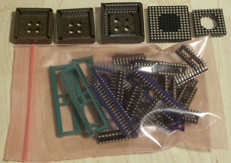
And some sockets - these makes the build much simpler and in case of chip failure, the machine easier to repair. But use good quality sockets - skip the cheap ones, specially if you plan to play around a lot with the hardware.
Note: there are more chips on the pictures than You actually need. When I was in the rush of buying from eBay, I got some more extra when I was on it. Also, there are some that I had before that I put into the same box.
2008-07-04: Waitning for the PCB, searching for parts...
GBA1000-links:
Pictures:
These will come when I have the board... ;-)