6AS7 mini-OTL Headphone Amplifier

This was a small side-step project that I made to test a few ideas around power filtering and to try out the 6AS7 tube. The original design was found at the HeadWize homepage and it was taken almost straight off with almost no changes to the amplifier design. The biggest change was made in the power supply. I also put the entire amplifier in a single box instead of splitting it in two as the original was done. It was little of a test to make a compact design.

The original project was made by Aren van Waarde and could be found here.
The power supply regulator was originally made by Helmut Ahammer and is used in a interesting OTL headphone amplifier design based on a E83CC/EL84 design.


The Amplifier Design
It is very simple - a high-gain common cathode amplifier built around a half E88CC makes up the input stage. The output stage is also simple - one half of the 6AS7 is built as a cathode follower with enough current to drive a 32ohm headphone directly.
This design uses just two tubes - both are dual-triodes where both channels shares the tubes (one channel for each half). The E88CC (6DJ8, 6922) is a medium-u, low voltage triode with rather low internal resistance. 6AS7 (6080) is a dual power-triode originally made for power regulations. Therefore, this tube have a very low u (=2) but also a very low internal resistance, making it a popular choise for OTL-designs.
The amplifier design was left almost untouched - the only change I made was to select a bigger value for the output capacitor. Instead of the original 220uF, I selected a 680uF low-ESR electrolytic. This should improve the low-frequency capability of the amplifier, but I haven't tried the 220uF so I can't say if it helps.

The power supply was the part that changed most compared to the original design. For the heater, I used a LM323 - a 5A/5V regulator instead of the LT1084 that are much more expensive. To get the required 6.3V for the heaters, I used two diodes of type 1N4148 to raise the reference for the regulator with 1.3V.
The high-voltage power supply went to a radical change due to a simple reason: a delayed package from USA. In the original design, a Triad choke was used for filtering the voltage - so I ordered one from a american web-site. During the time I was waiting to have it (and some other things too) I was assembling the rest of the amplifier. When it came to the power supply, I was still without the choke, so I started to look fo an alternative solution: electronic regulation. I found this a perfect chance to find a cheap solution to get high quality voltage and use the amp as a test object. I tested different solutions until I found one that both worked well and have low cost. The final design was also found at the HeadWise homepage, where it was used in a EL84-based headphone amplifier. It was running at 280V so I had to modify it to deliver 150V instead. That was simple - and the final result was perfect. The ripple and noise is almost impossible to see at my scope, even at the 5mV setting. And the amp draws almost 50mA of current.
This power design will be used in my next project - the budget Headphone OTL based at E88CC.

The interior of the amplifier. The audio-circuit is hardwired with prototyping board as support. The cathode resistors for the output tube are of the new type in TO220-package (partly visible left of the octal socket). All resistors in the amplifier circuit are 2W metal-film.

The large capacitor at the left side is the filter cap for the heater regulator. The regulator itself is bolted to the chassis and a large heatsink mounted at the top.
This is the high-voltage (150V) power supply unit. The upper, smaller board is the high-voltage regulator with slow-start (that replaces the choke).
Choose your tube - a Svetlana 6AS7G or a 6080WC from Philips ECG (made in US, military grade, marked JAN).
The small one is a Sovtek 6922 (E88CC), used in the input stage. Any E88CC/6DJ8/6922 can be used.
Complete interior of the amplifier. It looks little bit crowded, but it is rather spacy due to the box that are rather thick.
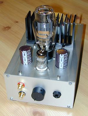
Complete amplifier, equipped with the Svetlana 6AS7. The visible capasitors are the 680uF used for the output.
Rear view of the amplifier. The heatsink is for cooling the heater regulator and the toroid transformer is for the high-voltage. The heater transformer is placed inside the box, right under the visible transformer.
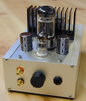
Here is the 6080 used instead.
Tube porn - a close up of the setup with Svetlana 6AS7G + Sovtek 6922.
More tube porn - this time the 6080 is in place.
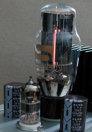
Here is a picture showing the open design of the 6AS7 electrode architecture. This tube (and the 6080) is a real glower - a perfect show-off tube.

Listening impressions

When listening to this amplifier, I used the same gear as for the OTL-amplifier based at 6SN7 I previously made. Also same music was used.
I tested with both output tubes that I got (6AS7G and 6080) but the difference wasn't that striking - both types sounded rather equal. The choice of tube will be more of how the amplifier should look like - the tubes are rather different in look. I prefer the Svetlana 6AS7G due to it's "coke-bottle" shape and it gives more visible glow.
The interesting thing was to compare this design with my own OTL amplifier that uses 6SN7 in a push-pull design. I found that the push-pull was more capable in handling low-impedance headphones, giving a more rich bass. Also, when using headphones with higher impedance like the Sennheiser HD575 (120 ohm), the sound was more detailed and with richer bass with the 6SN7 amplifier. That doesn't mean that this amplifier are bad - it has a very good sound that should satisfy most people and it is capable to handle most headphones avaiable (from 32 ohm). It is also simple to build compared with the 6SN7 amplifier and requires less parts, making it cheaper.

Schematics to download:

Amplifier Shows one channel only (other channel identical).
Power Supply Both high-voltage with regulator and heater.